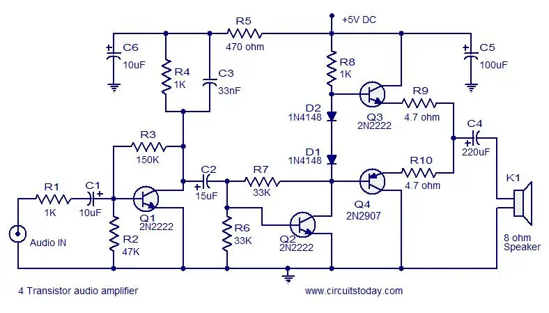

Class AB stands in between them and so it is used commonly in audio amplifier applications. Class A provides excellent signal reproduction but the efficiency is very low while Class C has high efficiency but the signal reproduction is bad. Where ζ is the efficiency, P out is the power output and P sis the power drawn from the power supply.Ĭlass A transistor amplifiers have up to 25% efficiency, Class AB has up to 55% can class C has up to 90% efficiency. Efficiency is usually expressed in percentage and the equation is ζ = (P out/ P s) x 100. In simple words it is a measure of how much power from the power supply is usefully converted to the output. Let R out = R in, then the equation 2 becomesĮfficiency of an amplifier represents how efficiently the amplifier utilizes the power supply. Where V out is the output voltage V in is the input voltage, Pout is the output power, P in is the input power, R in is the input voltage and R outis the output resistance. Let P out = V out / R out and P in = V in / R in. Voltage gain in decibel can be expressed using the equation, Av in dB = 20 log ( V out / V in) and current gain in dB can be expressed using the equation Ai = 20 log (I out / I in). Gain can be also expressed in terms of output voltage/input voltage or output current/input current. Here Pout is the power output and Pin is the power input. In decibel, the gain is expressed by the equation Gain in dB = 10 log (P out / P in). The gain in number is expressed by the equation G = P out / Pin. Gain can be simply expressed in numbers or in decibel (dB). It represents how much an amplifier can amplify a given signal. Gain of an amplifier is the ratio of output power to the input power. Points tagged P1 and P2 are the lower and upper half power points respectively. The frequency response of a single stage RC coupled transistor is shown in the figure below (Fig 3).

The bandwidth of a good audio amplifier must be from 20 Hz to 20 KHz because that is the frequency range that is audible to the human ear. In simple words, bandwidth is the difference between the lower and upper half power points. the points where the output power becomes half the peak output power in the frequency Vs output graph. Usually, the bandwidth is measured based on the half power points i.e. The range of frequency that an amplifier can amplify properly is called the bandwidth of that particular amplifier. In order to prevent the transistor amplifier circuit from loading the input voltage source, the transistor amplifier circuit must have high input impedance. Input impedance: Input impedance is the impedance seen by the input voltage source when it is connected to the input of the transistor amplifier.

The above given parameters are explained in the next section. In this article, we learn more about transistor amplifiers.Ī good transistor amplifier must have the following parameters high input impedance, high band width, high gain, high slew rate, high linearity, high efficiency, high stability etc. So, common emitter configuration is most commonly used in audio amplifier applications. Common emitter follower has a gain that is positive and greater than unity. In common base configuration has a gain less than unity and common collector configuration (emitter follower) has a gain almost equal to unity). common base (CB), common collector (CC) and common emitter (CE). As you know there are three transistor configurations that are used commonly i.e. Anyway the most common application we see in our day to day life is the usage of transistor as an audio amplifier. Transistors amplifiers are commonly used in applications like RF (radio frequency), audio, OFC (optic fibre communication) etc. An amplifier circuit which is purely based on a transistor or transistors is called a transistor amplifier. The input signal to an amplifier will be a current or voltage and the output will be an amplified version of the input signal. An amplifier is a circuit that is used for amplifying a signal.


 0 kommentar(er)
